Where Label Printing Is Headed: New Demands from Retail to E-commerce
Fast-moving retail shelve
Fast-moving retail shelve
Smarter workflows have be
Efficiency in logistics a
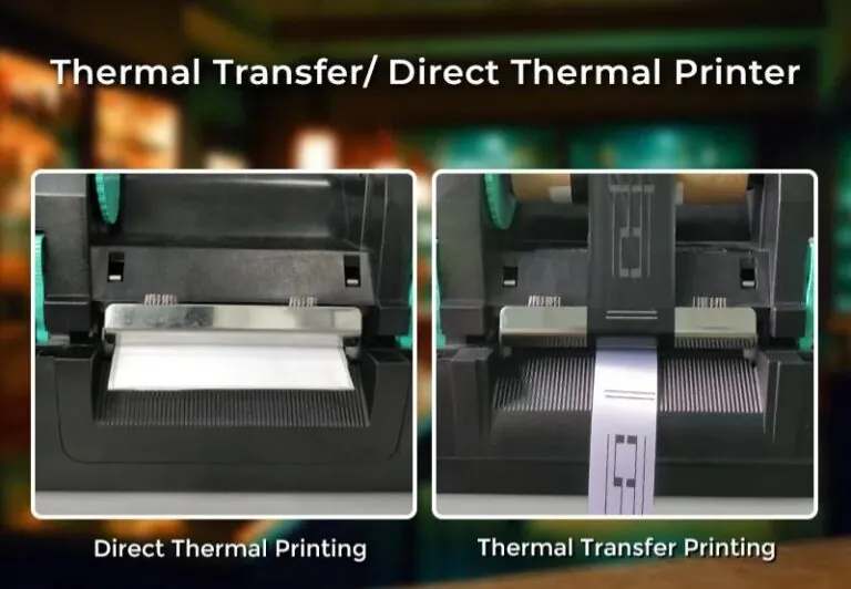
Thermal printing is a pri
Market competition and br
Controlling operational c
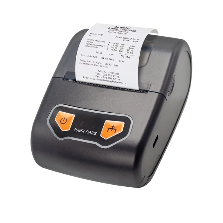
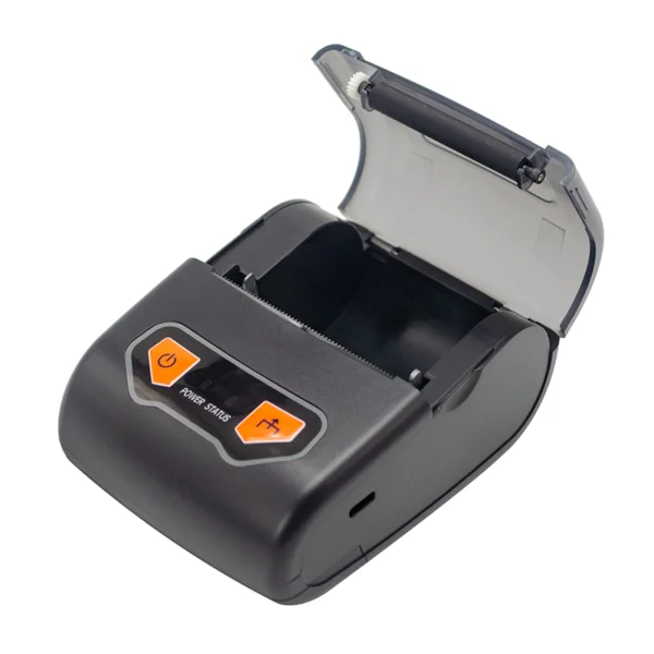
Mobile printing has becom
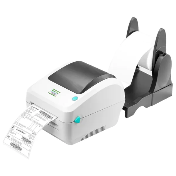
Warehouse efficiency depe

